
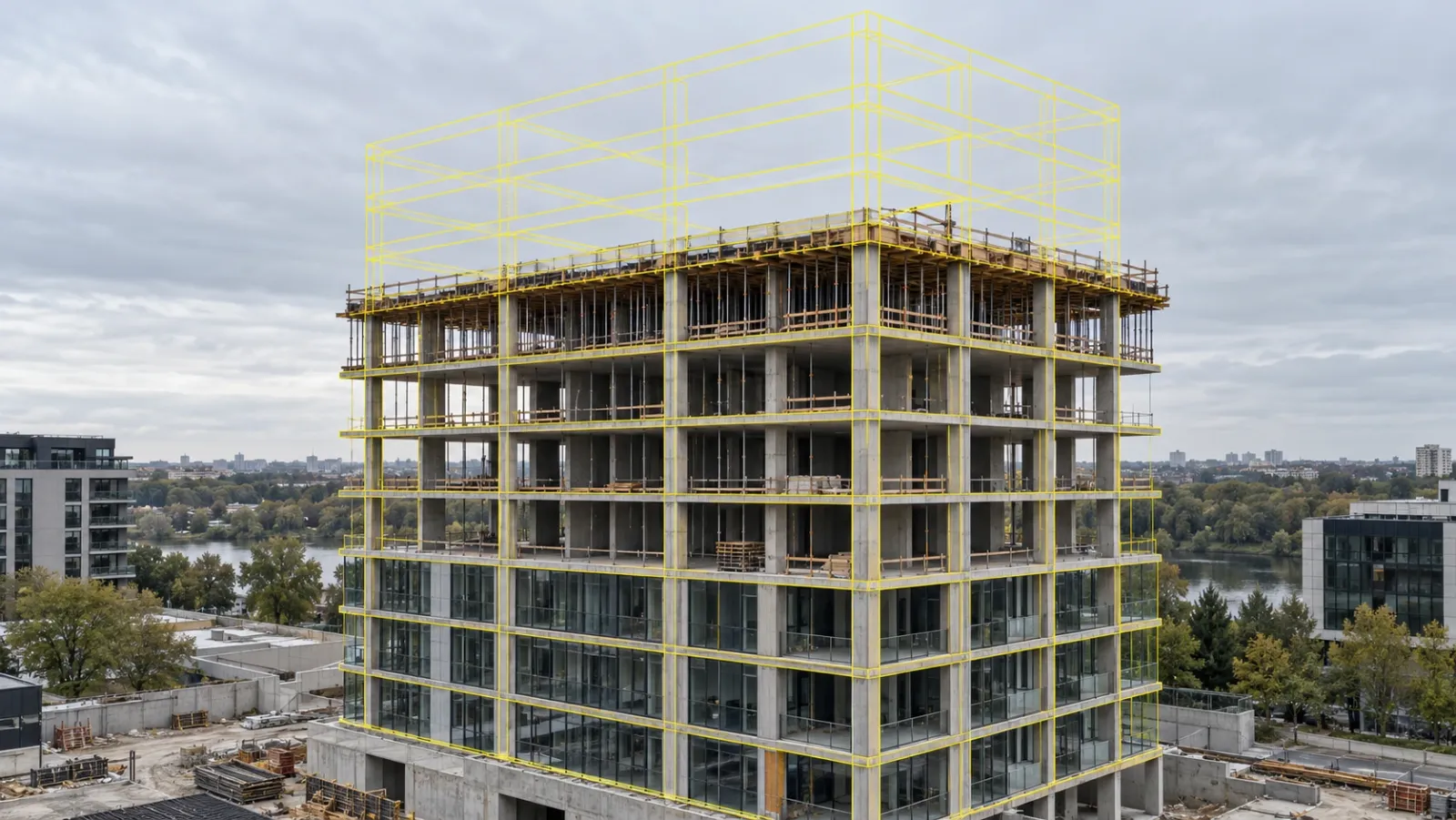
Key takeaways
- The Question: How do you check that what has been built matches the design, and then test whether it was built on time?
- The Answer: Start with geometry: capture the structure with a laser scan or drone survey, align it to the design model, and review deviations at the milestones where errors are still cheap to correct. Then use the same dated captures to test actual progress dates against the baseline programme.
- The YelloSKYE Angle: BIM IQ turns scans into as-built BIM at LOD 300–400 and overlays it on the design model, while Construct IQ captures progress; both sit in one time-linked record on DEX.
Two kinds of plan, and why the model comes first
On a construction project, "as-planned" means two things: the design model that fixes where every element should be, and the baseline programme that fixes when it should be built. "As-built" is the measured record of both. A useful comparison checks position first and dates second, because a column in the wrong place causes trouble for every trade that follows, whatever the programme says. BIM IQ is the YelloSKYE service built for that first check: it converts site scans into a model that can be laid over the design.
The two checks answer different questions. Geometry asks, "Is this the building we designed?" The programme asks, "Are we building it at the pace we agreed?" Both use the same raw material, a dated and located capture of the site, so it makes sense to plan them together. This guide spends most of its time on geometry, where the tools and terms are less familiar to many project teams, and then covers the programme check more briefly.
What a geometric check needs before anyone scans
A scan on its own proves very little. It becomes evidence only when it can be lined up with a known version of the design and judged against agreed limits. Three things need to be in place first.
A frozen model revision
Pick the model revision you are checking against and record its number on every report. If the design changes after an RFI or a site instruction, the model must be updated before the next comparison, or the team will spend its time chasing differences that the design team already approved.
Common survey control
The scan and the model must share a coordinate system. That means the same site grid and benchmarks the setting-out engineer used, with control points visible in the capture. Without it, the software can only make a "best fit", which hides a building that is consistently shifted or rotated.
Element tolerances in writing
A structural core, a precast stair landing and a blockwork partition do not need the same accuracy. Take the limits from the specification and list them by element type in the scan brief. Our guide on reality capture and BIM covers how to agree those limits with the engineers.
Picking the capture method for the question
The choice of sensor depends on how small a deviation you need to see and how much of the site you need to cover.
- Terrestrial laser scanning captures dense point clouds of a floor, core or plant room. It is the right tool for element-level questions: column positions, wall plumbness, opening sizes and cast-in items. See laser scanning in construction for how it works.
- Drone surveys cover the whole site quickly and produce orthomosaics, elevation models and point clouds. They suit footprint, levels and overall frame checks, and they reach roofs and upper edges that are slow to scan from the ground.
- A mix of both is common on large jobs: a drone pass for the full site, with a scanner sent to the zones where tolerances are tight or where prefabricated work will connect.
Whatever you choose, keep it consistent between milestones. A comparison is easier to trust when each capture uses the same method, control and processing settings as the last.
Reading a deviation heatmap
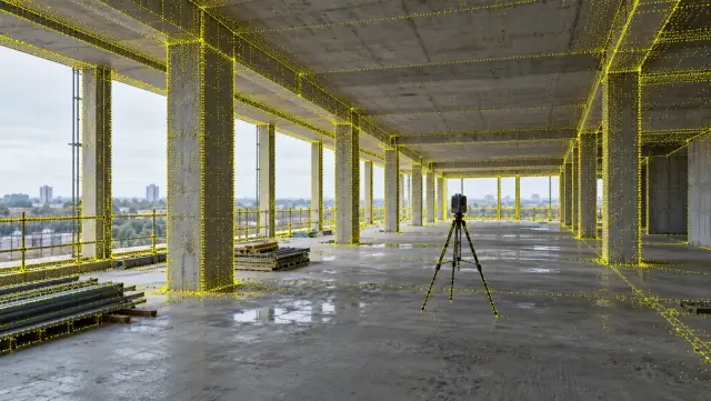
Once the point cloud is registered and aligned, software measures the distance from each captured point to the nearest modelled surface and colours it. The result is a heatmap laid over the model. It looks simple, but a few habits make it far more useful.
Read the legend before the picture
Colour bands are set by whoever produced the report. Check what distance each band represents and which direction counts as positive. On most reports, one colour family means the surface is in front of the model and the other means it is behind, with a neutral colour for anything within tolerance.
Look for patterns, not single spots
One red patch on a wall might be a ladder left in front of the scanner. A whole grid line drifting in the same direction points to a setting-out problem. A core that grows steadily further from vertical floor by floor points to a formwork or survey issue that will compound with every level.
Separate the false flags
Temporary works, stored materials and scanner shadows all show up as deviations. Before raising anything, open the raw point cloud for the flagged area and confirm the surface is the permanent element. The clash detection approach in our as-built vs BIM use case relies on this step, overlaying the scan in coordination software so genuine misalignments stand out from noise.
Check points by element and milestone
The value of a geometric comparison depends on timing. A deviation found before the next trade arrives can often be fixed in hours; the same one found after finishes are applied can mean demolition. The table below sets out sensible check points. Treat it as a starting template and replace the tolerance column with figures from your own specification.
| Element | When to capture | What to check | Typical capture | Tolerance source |
|---|---|---|---|---|
| Foundations and pile caps | After setting out and before the pour, then after the pour | Position against grid, top levels, holding-down bolt locations | Drone survey with ground control, plus scanner on bolt groups | Structural specification |
| Columns and walls | Each level, before the slab above is poured | Plan position, plumbness, section size | Terrestrial laser scan | Structural specification |
| Slabs and slab edges | After each pour, before facade brackets are fixed | Level, flatness, edge line, openings and penetrations | Laser scan, drone for roof slabs | Structural and facade specifications |
| Cores, shafts and stairs | Every few levels during the climb | Verticality, internal dimensions, door openings | Laser scan | Lift supplier and structural requirements |
| Embedded items and sleeves | After the pour, before services mobilise | Presence and position of sleeves, cast-in channels, plates | Laser scan | Services and structural drawings |
| Primary services | Before ceilings and risers close | Routes and clearances against the coordinated model | Laser scan or 360° capture | Coordinated services model |
| Facade and envelope | As panels go on, before sealing | Panel line, joint widths, alignment with slab edges | Drone and laser scan | Facade specification |
The pattern is the same throughout: capture the element when it is complete and before anything hides it or connects to it. Our pre-pour inspection guide covers the slab stage in more detail.
Logging a deviation and closing it out
A deviation report is only useful if each flagged element ends in a recorded decision. Run deviations through a register with the same rigour as any other quality issue.
What each entry should hold
Give every deviation an identifier, the element and grid reference, the model revision checked, the capture date, the measured distance against the allowed limit, and a screenshot of the heatmap with the raw cloud beside it. Link it to the capture on the shared platform so anyone can reopen the evidence.
Who decides, and the possible outcomes
The responsible engineer reviews each entry and chooses one of four outcomes: accept as built, accept and update the model, remediate on site, or redesign the connecting work. The project manager signs off any cost or time consequence. Keep the capture team out of the decision; their job is to measure accurately.
Proving it is closed
Remediated elements need a follow-up capture to show the fix worked. Only then should the entry close. Accepted deviations should be carried into the as-built model, so the handover record shows the building as it stands rather than as it was drawn. For how the record feeds handover, see our as-built survey guide.
The programme check: dates against site evidence
The second comparison looks at time. Here the as-planned record is the approved baseline programme, and the as-built record is the dated evidence of when each package actually began and was completed on site.
Reuse the geometric captures
The scans and drone surveys you take for model checks already carry a date and a location. Tagging them to programme activities gives the planner an objective view of progress without a separate site walk. Drone, 360° and fixed-camera captures fill in the weeks between scan milestones. In our construction progress capture work, weekly flights took more than 15 hours a week of manual reporting away from each site manager and cut stakeholder meetings from two hours to 30 minutes.
Status from what is visible
Agree what counts as "started" and "complete" for each activity in terms someone can see in a capture, such as "slab poured and formwork struck". Planners then update the programme from evidence rather than from verbal reports. Our guide to construction schedule updates covers the update cycle itself.
Where the two checks meet
A geometric deviation often becomes a programme problem. A misplaced core can hold up the lift installer for weeks while a fix is designed. When the deviation register and the programme share one record, the planner can see which open deviations sit ahead of time-sensitive work and push for decisions in the right order. The same dated evidence also helps when a payment claim is questioned: in our billing disputes use case, capture aligned to billing cycles meant 80% fewer site visits.
What each comparison should deliver
| Comparison | Inputs | Main outputs | Used by |
|---|---|---|---|
| Structure against model | Laser scans, drone point clouds, design model at a fixed revision | Registered point cloud, deviation heatmaps, deviation register, as-built BIM | Structural and services engineers, BIM coordinator, quality lead |
| Progress against programme | Drone, 360° and fixed-camera captures tagged to activities | Dated progress record, updated programme, variance notes | Planner, project manager, owner's representative |
| Handover record | Closed deviation register, final scans, accepted changes | As-built model and drawings for operations | Owner, facilities team |
How YelloSKYE supports both checks
BIM IQ converts point clouds from laser scanners and drone surveys into as-built BIM models at LOD 300–400, with scan-to-BIM accuracy of ±5 mm. It accepts data from Leica, FARO, Trimble, Matterport and other major scanner brands in formats such as .e57, .las, .rcp, .pts and .xyz, aligns the model to the project's coordinate system and overlays it on the design to show deviations and clashes. Models are ready for Revit and AutoCAD.
Construct IQ handles the time dimension with drone, 360° and fixed-camera capture that feeds progress reviews against the programme.
The DEX platform brings every photo, scan and BIM model into one time-linked portal. Teams can overlay CAD and BIM models on site visuals, measure from their desks and go back through months of history, so engineers reviewing deviations and planners reviewing progress are looking at the same evidence.
A starting checklist
- Fix the model revision and programme baseline you will compare against, and record both on every report.
- Confirm the scan uses the same survey control as the setting-out.
- List tolerances by element type from the specification and put them in the scan brief.
- Map capture milestones to the points where each element will be hidden or connected to.
- Set up a deviation register with owners, outcomes and a closure capture.
- Tag every capture to grid, level and programme activity so the planner can reuse it.
- Carry accepted deviations into the as-built model as you go, not at the end.