Ground Sample Distance (GSD): How to Calculate It and What Your Project Needs
By Kush Agarwal, President and CEO, YelloSKYE. Published .
Executive Summary
- The Question: What is ground sample distance, how do you work it out, and what value does each kind of drone deliverable need?
- The Answer: GSD is the ground size of one image pixel. It is set by flight height above ground, the sensor's pixel size and the lens focal length, and it can be calculated before anyone flies. Pick it from the smallest thing you need to measure, then remember it describes detail, not positional accuracy.
- The YelloSKYE Angle: Survey IQ captures at centimetre-level GSD for land and terrain work, and pairs that resolution with RTK-GNSS positioning and ground control so the detail also sits in the right place.
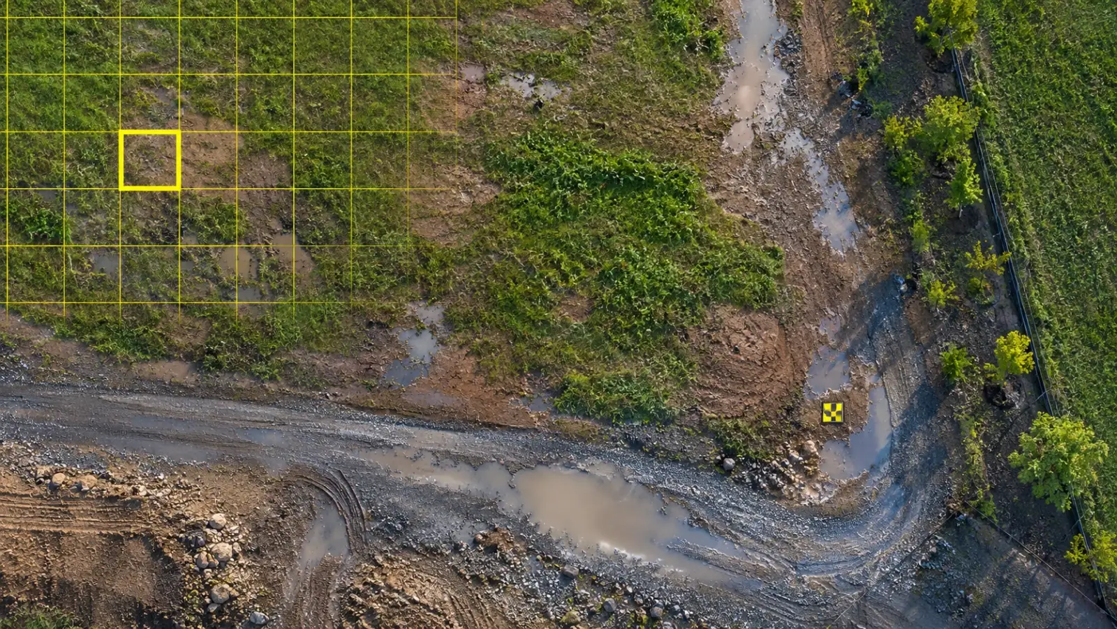
Ground sample distance (GSD) is the distance on the ground covered by one pixel in an aerial image. On a map flown at a 2 cm GSD, every pixel stands for a square of ground 2 cm on each side, and nothing much smaller than that can be seen or measured. GSD is the first number to fix when planning a mapping flight, because it decides what the finished orthomosaic, terrain model and point cloud will be able to show.
At YelloSKYE, land and terrain surveys run through Survey IQ, where flights are planned around the resolution each deliverable needs. This guide explains what GSD measures, the three things that set it, how to calculate it step by step, which values suit which deliverables, and why a fine GSD on its own does not make a map accurate.
What GSD actually describes
Every digital image is a grid of pixels. When the camera points at the ground, each pixel collects light from a small patch of that ground, and GSD is the width of that patch. It is usually quoted in centimetres per pixel.
A few points are worth keeping in mind:
- Smaller is finer. A 1 cm GSD holds four times as many pixels over the same area as a 2 cm GSD, because the resolution doubles in both directions.
- It is a planned, nominal value. The figure on a flight plan assumes the camera points straight down at flat ground from a fixed height. Real images vary a little across the frame and with the terrain.
- The map inherits it. An orthomosaic is usually produced at, or close to, the GSD of the source images. Resampling a map to smaller pixels does not add detail that the camera never captured.
- It is not the same as accuracy. GSD says how much detail there is. Whether that detail sits in the right place is a separate question, covered later in this guide.
The three things that set GSD
GSD comes from simple geometry: the size of a sensor pixel, projected through the lens onto the ground.
| Factor | Effect on GSD | In practice |
|---|---|---|
| Height above ground | Doubling the height doubles the GSD | The setting most often changed between projects |
| Sensor pixel size (pitch) | Smaller pixels give a finer GSD at the same height | Fixed by the camera; larger sensors often have more pixels |
| Lens focal length | Longer focal length gives a finer GSD at the same height | Fixed on most mapping cameras; narrower view per photo |
Pixel pitch is the physical width of one pixel on the sensor, which is the sensor width divided by the number of pixels across it. That gives the standard formula:
GSD (cm/pixel) = (sensor width in mm × height above ground in m × 100) ÷ (focal length in mm × image width in pixels)
The same relationship can be read the other way round. If you know the GSD you need, you can solve for the height at which to fly.
A worked GSD calculation
Take a mapping camera with a common 1-inch-type sensor:
- Sensor width: 13.2 mm
- Image width: 5,472 pixels
- Image height: 3,648 pixels
- Focal length: 8.8 mm
Step 1: pixel pitch
13.2 mm ÷ 5,472 pixels = 0.00241 mm, or about 2.4 micrometres per pixel.
Step 2: GSD at 100 m
(13.2 × 100 × 100) ÷ (8.8 × 5,472) = 132,000 ÷ 48,154 ≈ 2.74 cm per pixel.
Step 3: ground footprint of one photo
Multiply the GSD by the image dimensions. 2.74 cm × 5,472 pixels ≈ 150 m across, and 2.74 cm × 3,648 pixels ≈ 100 m along the direction of flight. Each photo covers roughly 150 m by 100 m of ground.
Step 4: solve for a target GSD
Suppose a topographic survey needs about 1.5 cm per pixel. Because GSD scales directly with height, the required height is 100 m × (1.5 ÷ 2.74) ≈ 55 m above ground.
The same camera at different heights
| Height above ground | GSD | Photo footprint (across × along) |
|---|---|---|
| 20 m | 0.55 cm | 30 m × 20 m |
| 40 m | 1.10 cm | 60 m × 40 m |
| 60 m | 1.64 cm | 90 m × 60 m |
| 80 m | 2.19 cm | 120 m × 80 m |
| 100 m | 2.74 cm | 150 m × 100 m |
| 120 m | 3.29 cm | 180 m × 120 m |
Height limits are set by each country's aviation rules. Many national aviation authorities, for example the FAA in the US and the CAA in the UK, cap routine drone flights at around 120 m above ground, so check the local rules before planning a coarse, high-altitude capture.
How terrain and structures change GSD
A flight plan usually holds the drone at a constant height above its take-off point. GSD, however, depends on the distance to the ground directly below the camera. On a sloping site those are not the same.
Using the camera above, imagine a parcel with 30 m of relief, with the drone taking off from the lowest corner and flying at 100 m. Over the low corner the GSD is 2.74 cm. Over the highest ground the camera is only 70 m above the surface, so the GSD there is about 1.92 cm. The map is sharper on the hill than in the valley, and, because each photo now covers less ground on the high side, the overlap between neighbouring photos drops there too, which can cause gaps.
Two common responses:
- Terrain-following flight. The drone adjusts its height to stay a fixed distance above a terrain model, keeping GSD and overlap consistent.
- Planning for the highest point. Set overlap high enough that coverage still holds on the highest ground, accepting finer resolution there.
Buildings and tall structures do the same thing on a smaller scale. A roof is closer to the camera than the street beside it, so roof detail is finer and overlap on the roof is lower. For planning the full mission around these effects, see our guide to drone mapping flight planning.
What else limits real resolution
GSD is the theoretical best case. Several things can make a map less sharp than its stated GSD:
- Motion blur. At 10 m/s with a 1/1000 s shutter, the drone moves 1 cm while the shutter is open. At a GSD of about 1 cm, that is a full pixel of smear. Slow the aircraft or shorten the exposure for fine work.
- Focus and lens quality. A soft lens spreads a point across several pixels, so the effective detail is coarser than the pixel count suggests.
- Low light and noise. Dull conditions force slower shutters or higher sensitivity, both of which soften detail.
- Compression. Heavily compressed images lose fine texture that the processing software uses to match photos.
- Thermal cameras. A thermal sensor has a small fraction of the pixel count of a visible-light camera, so flying at an equal height yields a much coarser GSD. Thermal flights are planned separately.
What GSD each deliverable needs
The right GSD comes from the smallest feature you need to identify or measure. As a working habit, that feature should span several pixels, not one. The ranges below are typical starting points for planning, not fixed rules; confirm them against the project's own tolerances.
| Deliverable | Typical GSD | What drives it |
|---|---|---|
| Progress orthomosaic and visual record | 2–5 cm | Recognising work fronts, materials and site layout |
| Site logistics and layout overlays | 2–4 cm | Placing laydown areas, roads and footprints against a plan |
| Stockpile and earthwork volumes | 1.5–3 cm | Clean surface edges and well-defined toes and crests |
| Topographic survey and contours for design | 1–2.5 cm | Kerb lines, breaklines and fine level changes |
| Corridor mapping for roads, pipelines and rail | 2–3 cm | Balance between detail and covering long distances |
| Paved surface condition | Under 1 cm | Seeing cracks, potholes and joint defects |
| Facade and structural inspection | A few millimetres | Hairline cracks, fixings and sealant joints, captured close and often obliquely |
Volumes
For earthworks, resolution matters most at the edges of each surface, where the toe of a stockpile or the crest of a cut meets the ground. On YelloSKYE's earthwork volumetric analytics project, drone topography flown every few days let the DEX platform check volumes against the design grading plan, replacing a two-week manual survey cycle with results in hours.
Topography
For design surveys, fine GSD helps pick out breaklines such as ditch edges and kerbs. The rest of the scope, from contour interval to ground infill, is set out in our guide to drone topographic surveys.
Inspection
Inspection imagery is usually captured much closer than mapping flights. YelloSKYE's facade inspection from a desk workflow relies on that detail: the DEX Facade view presents every elevation as a separate detailed map for a chosen date, where a defect can be measured and checked against an earlier capture.
Why GSD is not accuracy
This is the most common misunderstanding about drone maps. GSD and accuracy measure different things, and improving one does not automatically improve the other.
| Ground sample distance | Accuracy | |
|---|---|---|
| What it describes | How much detail each image holds | How close measured positions are to the truth |
| What sets it | Height, sensor and lens | Positioning, ground control, overlap, processing and datum |
| When it is known | Before the flight, by calculation | After processing, by comparison with check points |
| Typical unit | Centimetres per pixel | Centimetres of error, usually per axis |
| Failure looks like | A blurry map | A sharp map in the wrong place |
A drone flown low over a site with no corrected positioning and no ground control can produce a beautifully detailed map that is shifted a metre or more from its true coordinates. Detail does help: a well-defined target can be located more precisely in a fine image, and in a well-controlled survey horizontal error is often in the region of one to two pixels, with height error somewhat larger. But the tie to the real world comes from RTK or PPK positioning and ground control, not from resolution. Our guide to drone mapping accuracy explains how to read the accuracy figures that should come with a survey.
The cost of going finer
Finer GSD is not free. Halving the GSD means halving the height, so each photo covers a quarter of the ground. For the same site, that means roughly four times as many photos, twice as many flight lines, more batteries, longer processing and larger files to store and share. On a large parcel, the difference between 3 cm and 1.5 cm can turn a single day's flying into several.
That is why GSD should follow the deliverable, not the other way round. On YelloSKYE's pre-acquisition land surveys, Survey IQ captures geotagged imagery at centimetre-level GSD across parcels of hundreds of acres in a single mobilisation, which gives enough detail for boundary checks, terrain models and preliminary cut and fill without over-flying the site.
How YelloSKYE plans resolution
Survey IQ plans each flight around the deliverables the project needs, then ties the imagery down with RTK-GNSS positioning and ground control points for sub-5 cm horizontal and vertical accuracy. Outputs are published to the DEX platform, where the orthomosaic, terrain models and point cloud sit on one timeline with earlier captures and can be measured from a browser. Keeping the same GSD and flight settings from one survey to the next is part of what makes those comparisons meaningful, and the stitched map itself is the subject of our orthomosaic guide.
GSD planning checklist
- Name the smallest feature each deliverable must show, and make sure it spans several pixels.
- Calculate GSD from the actual camera: sensor width, image width in pixels and focal length.
- Solve for flight height from the target GSD, then check it against local height limits.
- Allow for terrain: use terrain-following flight or plan overlap for the highest ground.
- Control motion blur by matching speed and shutter to the GSD.
- Keep GSD consistent between repeat flights so maps compare cleanly.
- Do not treat GSD as accuracy: plan positioning, control and check points separately.
Frequently asked questions
What is ground sample distance in drone mapping?
Ground sample distance (GSD) is the size of the patch of ground represented by one pixel in a drone image or map. A GSD of 2 cm means each pixel covers 2 cm by 2 cm on the ground. The smaller the number, the finer the detail that can be seen and measured.
How do you calculate GSD?
Multiply the sensor width by the flight height above ground, then divide by the lens focal length multiplied by the image width in pixels. With sensor width and focal length in millimetres and height in metres, multiplying the result by 100 gives GSD in centimetres per pixel. Many flight planning apps do this automatically once the camera is selected.
What is a good GSD for a drone survey?
It depends on the deliverable. Visual progress maps work at a few centimetres per pixel, earthwork volumes and topographic surveys usually need finer resolution, and crack or surface defect inspection needs millimetre-level detail. Choose the coarsest GSD that still shows the smallest feature you need to measure.
Does a smaller GSD make a drone map more accurate?
Not by itself. GSD describes how much detail the images hold, while accuracy describes how close the map is to true positions. A very sharp map can still sit a metre away from its correct coordinates if it has not been tied down with corrected positioning or ground control.
Why does GSD change across a hilly site?
GSD depends on the distance between the camera and the ground. If a drone holds one height above its take-off point, it is closer to hilltops and further from valleys, so the resolution varies across the map. Terrain-following flight keeps the height above ground, and therefore the GSD, more consistent.