
Key takeaways
- The Question: What does BIM level of development mean, how do LOD 100 to 500 differ, and what LOD should a project ask for when the model will be used to track progress and produce as-built records?
- The Answer: LOD is a promise about how reliable each model element is, set element by element and stage by stage in the BIM execution plan. Geometry is only half of it: level of information, element breakdown and field verification decide whether a model can actually support tracking and handover.
- The YelloSKYE Angle: BIM IQ models existing and as-built conditions from laser scans and drone point clouds at LOD 200 to LOD 400, and the DEX platform lays design models over dated site captures so the LOD you specified can be checked against what was built.
BIM level of development (LOD) is a scale, usually written as LOD 100, 200, 300, 350, 400 and 500, that tells everyone using a model how far each element has been developed and how much they can trust its size, position and data. It is not a measure of how good a model looks. A rendered wall can be LOD 100 if nobody has decided its build-up yet, and a plain grey box can be LOD 300 if its dimensions are fixed. For teams that use models to verify construction, LOD decides what can be checked and what cannot, which is why YelloSKYE's BIM IQ states the LOD of every as-built model it delivers.
Below: each level in turn, LOD versus level of information, writing LOD into a BIM execution plan, the LOD that progress tracking and as-builts need, and what to do when parts of the model do not exist yet.
Development, not detail
The term began as "level of detail", which caused confusion because detail suggests appearance. The American Institute of Architects introduced the level of development idea in its E202-2008 BIM protocol exhibit, and the BIMForum in the United States now publishes a Level of Development Specification that interprets each level for hundreds of element types, organised by the Uniformat classification. Other countries use their own frameworks, but most borrow the same numbers.
The key shift is from appearance to reliability. Each level answers one question: if I take a dimension, a position or a quantity from this element, what can I safely do with it?
Three consequences follow, and most LOD disputes come from forgetting one of them:
- LOD belongs to elements, not to models. A "LOD 300 model" is shorthand that hides the real requirement. Columns may be at 350 while ceilings are still at 200.
- LOD is tied to a stage. The same duct run might be required at 200 at concept design, 300 at technical design and 400 before fabrication.
- LOD says nothing about accuracy against the real building. A beautifully developed element can still sit 40 mm from where the steel was actually erected. That is a separate specification.
LOD 100 to 500 at a glance
| LOD | What you can rely on | What you should not assume | Typical point in the project |
|---|---|---|---|
| 100 | That something of this kind is intended in roughly this area; areas and volumes for early cost plans | Any real size, shape or position | Feasibility and concept |
| 200 | Approximate size, shape, position and orientation of a generic object | That its dimensions are final or that it can be measured from | Concept and early design |
| 300 | Designed size, shape, location and orientation; quantities that can be measured from the model | How it connects to neighbouring elements or how it will be fixed | Technical design, tender |
| 350 | Everything at 300, plus the interfaces with other elements: supports, connections, clearances | Fabrication detail or the exact product | Coordination and pre-construction |
| 400 | Enough detail to fabricate and install, including fixings, assembly and product-specific geometry | That it has been checked against what was built | Shop drawings, prefabrication |
| 500 | That the element's size, location and data have been verified on site | Anything not covered by the stated verification method | Handover and operation |
Two levels need a note.
Why LOD 350 exists
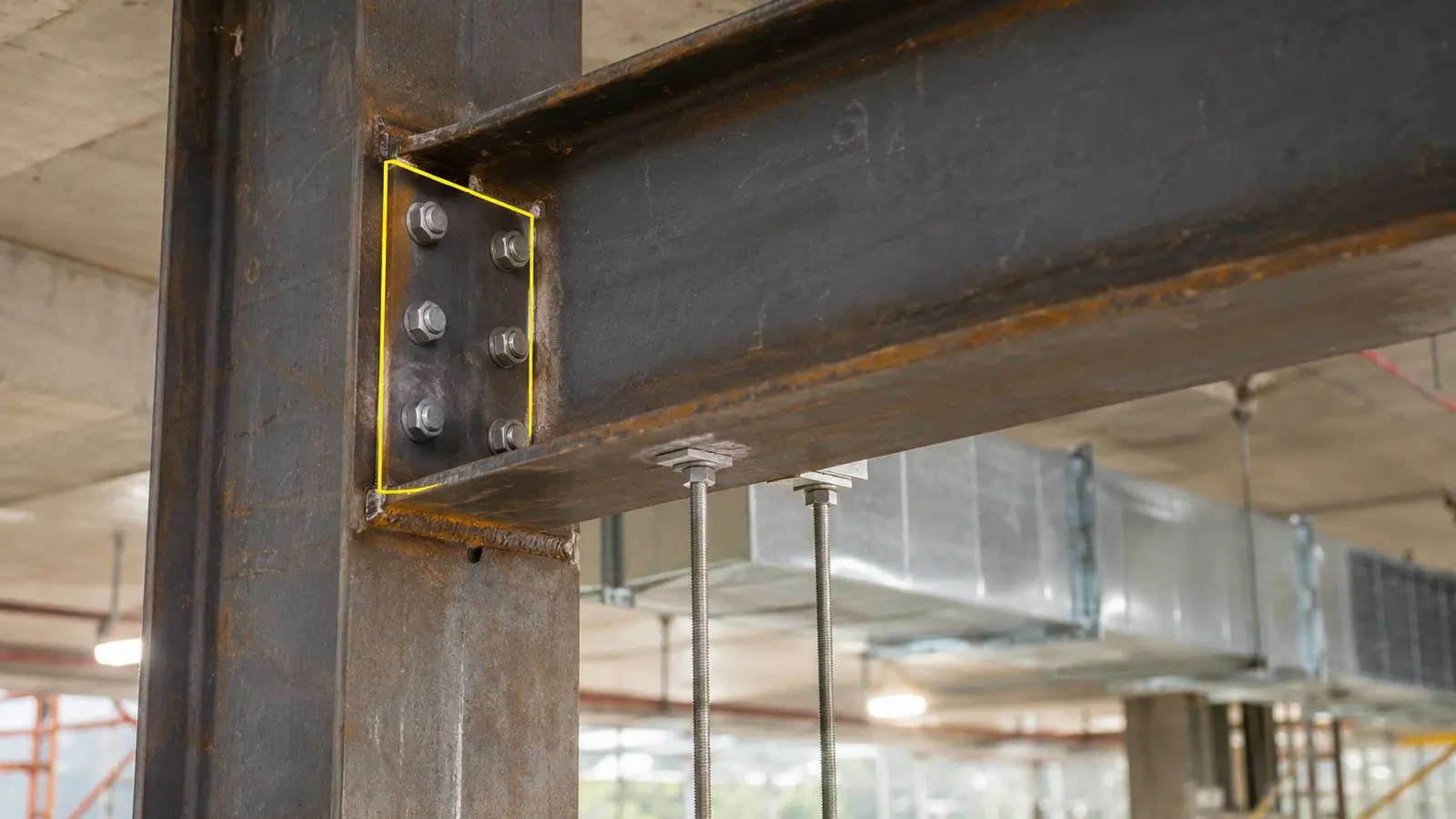
Many coordination problems happen at the joint between elements rather than in the elements themselves: the hanger that lands on a beam flange, the sleeve that misses the slab opening, the bracket that needs a clear zone around it. LOD 350 was added to make those interfaces part of the deliverable. If clash detection is a contractual expectation, ask for 350 on structure and main services, not just 300. How those clash cycles run is set out in BIM coordination in construction.
Why LOD 500 is left out of some specifications
LOD 500 does not describe more geometry than 400. It describes a different kind of certainty: someone has measured the installed element and confirmed it. Because that is a statement about field verification, the BIMForum specification does not define it at all, and many teams prefer to replace the word "LOD 500" in contracts with a plain description of what must be verified, how and to what tolerance.
LOD and level of information
A model element carries two kinds of content: geometry and data. Level of development blends them, but several frameworks pull them apart. The older UK standard PAS 1192-2 used "level of definition", made up of level of model detail (graphics) and level of information (data). The international ISO 19650 series replaced both with "level of information need", described in EN 17412-1 as three strands: geometrical information, alphanumerical information and documentation.
The separation is useful because the two rarely mature at the same pace. A fire door can have fixed geometry long before anyone knows its supplier, ironmongery set or certification reference.
| Stage | Geometry of a fire door | Information attached to it |
|---|---|---|
| Concept | A generic opening in the wall | Fire rating required by the strategy |
| Technical design | Correct leaf size, frame and swing | Rating, acoustic rating, ironmongery schedule reference |
| Construction | Product-specific frame and leaf | Manufacturer, product code, installer, installation date |
| Handover | Position confirmed on site | Certificate, maintenance interval, link to inspection record |
When you write requirements, describe both strands. "LOD 300" alone tells a modeller how to draw a door but not that facilities management will need its certificate attached by handover.
Specifying LOD in the BIM execution plan
The BIM execution plan (BEP) is where good intentions about LOD turn into checkable deliverables. The usual tool is a model element table, sometimes called a model progression specification: a grid of element groups against project stages, with the LOD required and the party responsible in each cell.
A workable process looks like this:
- Start from the uses, not the levels. List what the model must support at each stage: cost plans, clash detection, prefabrication, progress tracking, as-built handover. Each use implies a minimum LOD for certain elements.
- Break elements down to the level the uses need. Group by classification, but split groups where the uses differ. Primary ductwork may need 350; terminal grilles may stay at 200.
- Name an author for every cell. The design team may own an element up to 300 and a trade contractor take it to 400. The hand-over between them should be dated.
- Pair LOD with a level of information. For each group, list the properties that must be filled in by each stage, such as zone, system, activity code or product reference.
- State accuracy separately. Where the model will be compared with the built work, give a tolerance per element group. The USIBD Level of Accuracy Specification is a widely used reference for those bands.
- Agree how compliance is checked. A model that claims LOD 300 should be reviewed against the definition at each stage gate, with a short report of elements that fall short.
Asking for the highest LOD everywhere is the most common and most expensive mistake. Modelling effort rises steeply between 300 and 400, and most of that effort is wasted on elements nobody will fabricate from.
The LOD a progress-tracking model needs
For progress tracking the question is no longer whether an element is designed well enough to build, but whether it is broken down well enough to show how far the build has gone. Structure matters more than geometric richness. A model at LOD 300 with the right breakdown will support progress tracking far better than one at LOD 400 where a whole floor of partitions is one object.
| Tracking question | What the model must provide | Common gap |
|---|---|---|
| Is this wall complete? | Each wall as a separate element per room or zone | Walls modelled as long runs through several rooms |
| Which stage of the wall is done? | Separate elements or properties for framing, first side, services, second side | One element for the whole build-up |
| Which trade installed it? | A property naming the trade package or activity code | Only a type name such as "Partition Type 3" |
| Where is it? | Zone, level and gridline properties that match the schedule | Zones in the model named differently from the programme |
| How much is left? | Measurable quantities per element | Generic objects with no area or length |
| Is it the same element as last week? | A persistent unique identifier | Elements deleted and redrawn after every revision |
Linking elements to schedule activities is often called 4D. On YelloSKYE's DEX platform, the progress versus plan view compares site captures with the 4D schedule, and the platform verifies progress against BIM models, schedules and BOQs. That comparison is only as good as the model breakdown, so put the tracking properties in the model element table from the start.
Once the model is broken down this way, the weekly comparison itself is described in as-built vs as-planned.
The LOD an as-built model needs
An as-built model is a record of what is there, so its value comes from verification rather than development. Two routes produce one: updating the design model as changes happen and checking it against the building, or modelling the building directly from a laser scan or drone point cloud.
For either route, specify three things per element group:
- The LOD, usually lower than the construction model for finishes and higher for anything a maintenance team will need to locate precisely, such as services in ceiling voids and risers.
- The accuracy, stated as a tolerance and the method of checking it.
- The information, meaning the properties and documents the owner's systems will import.
For as-built work, BIM IQ models elements at between LOD 200 and LOD 400, choosing the level by the capture method used on site and the job the model has to do. Its sources are laser scans and drone point clouds, and it works with Revit, Navisworks and ArchiCAD, and exchanges models through IFC. In our clash detection example, each structural milestone is scanned and checked against the design model, which shows up deviations before the following trade is on site. The renovation use case shows the same method used on an existing building before redesign. The full modelling workflow is in our guide to what is Scan to BIM.
Working with an incomplete model
On most real projects, some trades start work before their part of the model exists. Packages are released in stages, specialist contractors are appointed late and design changes push modelling behind the programme. Waiting for a complete model is rarely an option. Pretending the gaps are not there is worse, because any progress figure calculated only from modelled elements quietly overstates how far the job has come.
A disciplined approach treats missing scope as a managed risk.
Keep a register of unmodelled scope
List every schedule activity with no matching model elements, the party responsible for modelling it and the date its work is due to start. Sort it by start date and review it in design meetings, so the most urgent gaps are closed first.
Hold the scope with placeholders
Where geometry is not ready, add simple LOD 100 or 200 elements carrying the expected quantity, zone and activity code. They will not support clash detection, but they keep the scope in the totals so percentages stay honest. Mark them clearly so nobody mistakes them for designed elements.
Record progress against the placeholder
Until the real elements arrive, track the activity by measured quantity or area and keep the record with the placeholder. When the trade model is issued, replace the placeholder and carry the recorded progress over to the new elements.
Keep capturing the site regardless
A dated visual record of unmodelled areas means progress can be confirmed after the fact, once the model catches up. On DEX, drone, 360° and laser scan captures sit on one timeline, so a team can return to the walk from the week an activity started and check it against the newly issued model.
Report the modelled share
Add one line to the progress report: the proportion of scheduled scope that is modelled at the LOD the tracking needs. It makes the size of the gap visible to the people who can fund or push the modelling.
A short LOD checklist
- List the uses of the model at each stage before choosing any LOD.
- Build a model element table with an LOD, a level of information and a named author per element group and stage.
- Reserve LOD 350 for interfaces that will be coordinated and LOD 400 for elements that will be fabricated from the model.
- Replace "LOD 500" in contracts with what must be verified, how and to what tolerance.
- Split elements the way they are installed and give each a persistent identifier, zone and activity code.
- Keep a register of unmodelled scope with placeholders that carry quantities.
- Check stated LOD against the definition at every stage gate, and check as-built elements against a scan or survey before handover.