
Key takeaways
- The Question: When is laser scanning worth the cost on a data centre or other mission-critical build, what should be scanned, and how often?
- The Answer: Scanning pays where geometry is unforgiving: dense service zones, slabs that carry raised floors and heavy plant, and every interface a prefabricated module has to meet. Scan at defined events, especially before modules are set and before services are hidden, and turn the scans into deviation reports and commissioning records rather than raw files.
- The YelloSKYE Angle: BIM IQ registers scans from the major scanner brands to model coordinates, compares them with the design and models as-built conditions, and DEX keeps each scan beside the drone, 360° and fixed-camera captures from the same week. We have no data centre case study; this guide applies methods we use on other complex buildings.
Laser scanning on a data centre is a measurement tool for the parts of the building where there is almost no room for error: crowded service zones, slabs that must carry raised floors and heavy equipment, and the interfaces that prefabricated power and cooling modules have to land on. Used well, it is not a general survey but a series of targeted scans timed to the moments when a geometric mistake is still cheap to fix. YelloSKYE turns that scan data into deviation checks and as-built models through BIM IQ.
This guide is about the data centre case specifically. How scanners work, the difference between terrestrial, mobile and aerial systems and what controls accuracy are covered in our guide to laser scanning in construction.
Why mission-critical builds raise the stakes
Most buildings tolerate a small amount of geometric drift. A partition a little off line is corrected in the finishes. Data centres, along with hospitals, laboratories and semiconductor plants, have features that remove that slack.
| Feature of the build | Why it raises the stakes | What a scan checks |
|---|---|---|
| Dense services | Busway, cable tray, chilled water, fire suppression and containment compete for the same ceiling and floor zones | Whether installed routes leave the clearances the design assumed |
| Prefabrication | Power skids, modular plant and pre-assembled racks are built off site to the model | Whether plinths, embeds, openings and connection points are where the modules expect them |
| Repetition | Halls and rooms are copies of each other | Whether an error in the first hall is about to be repeated in the next |
| Heavy, level-sensitive equipment | Raised floors, racks and large plant need flat, level bearing surfaces | Slab surface shape before pedestals and plinths go in |
| Compressed programmes | Trades overlap and there is little float to absorb rework | Problems early enough to fix without moving the ready-for-service date |
| Live operation after handover | Opening up a running hall is slow, risky and tightly controlled | A complete geometric record before the space closes |
The common thread is cost of correction. On these projects a deviation found during installation can hold up a module delivery, a commissioning test or a tenant's start date, which is why many owners write scanning into their requirements for critical areas.
What to scan, room by room
Scanning every square metre at the same intensity wastes time. Focus effort where geometry decides whether the next trade can proceed.
| Area | What to capture | Typical question |
|---|---|---|
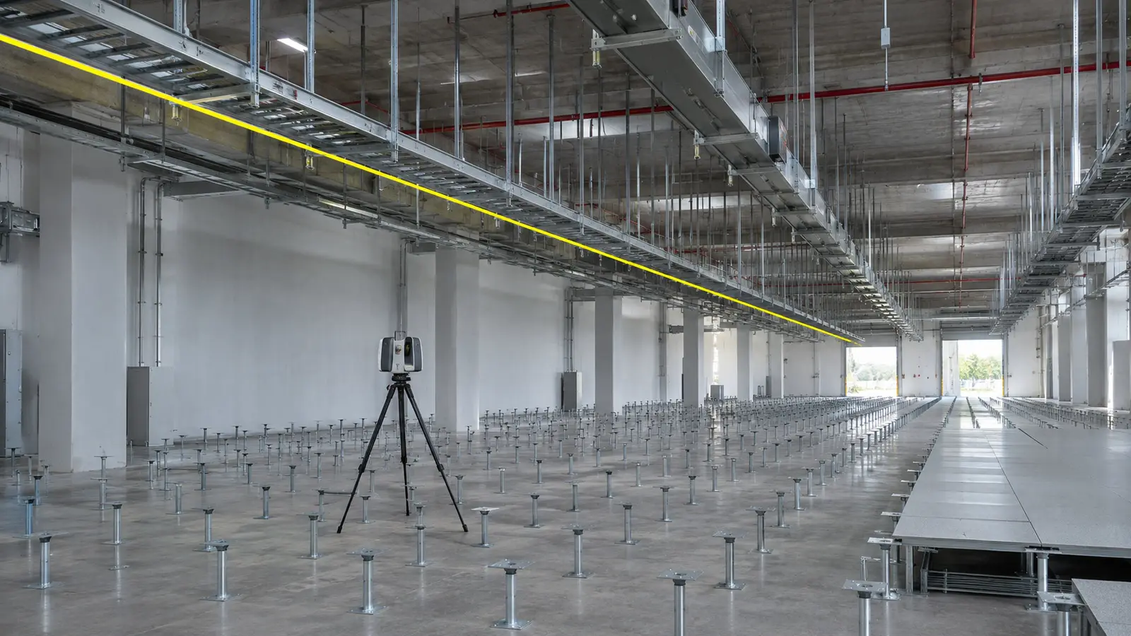
| Data halls | Slab surface, pedestal grid, overhead support steel, containment, cable tray and busway routes | Is there a clear path for every service, and will the raised floor sit level? |
| Electrical rooms | Switchboard and UPS positions, cable entry points, busway routes, trench and floor openings | Do the room and its openings match the equipment shop drawings? |
| Plant yards and roofs | Plinths, anchor bolts, pipe racks, support steel, crane and delivery access | Will chillers, generators and modules land on their supports without packing or cutting? |
| Risers and penetrations | Slab and wall openings, sleeves, fire-stopping zones | Are openings in the right place and big enough for the planned services? |
| Delivery routes | Corridors, doors, ramps, lift shafts and turning spaces | Can the largest items physically be moved to their final position? |
The delivery route check is easy to forget. Large plant is often sized to fit with very little margin, and a temporary obstruction or a door frame built slightly narrow can stop an installation for days.
Scanning before prefabricated modules arrive
Prefabrication moves work into a factory where quality is easier to control, but it also moves risk to the moment of installation. The module is made to the model; the site may not be. A scan of the landing zone before the module ships closes that gap.
A practical sequence:
- Agree the interface list. For each module, list every point where it meets the building: anchor bolts, embed plates, plinths, cable and pipe entry points, openings and support steel. Give each a tolerance agreed with the module supplier.
- Scan the landing zone once the structure and supports are complete, registered to the same coordinates as the design model.
- Compare against the model and the module's shop drawings, not only the general arrangement. The supplier's drawings show what the module actually needs.
- Issue a deviation list with each interface marked pass or fail, the measured offset and a photo or scan view of the location.
- Decide the fix for each failure: correct the site, adjust the module in the factory, or accept with a documented allowance.
- Re-scan corrected interfaces before the module is released for delivery.
- Scan the installed module so the record shows what was actually set.
The same method suits any item made off site to fit an existing structure, from pre-assembled pipe racks to modular electrical rooms.
Slab surfaces under raised floors and heavy plant
Raised-floor systems and heavy equipment depend on the slab beneath them. Specifications usually set flatness and levelness requirements and a method for checking them, such as ASTM E1155 for F-numbers in the United States or the Concrete Society's TR34 for floors carrying racking in the UK. Rules and methods differ by country and by owner.
A scan does not replace the specified test, but it adds two things. It shows the whole surface as a continuous colour map rather than a set of sampled lines, so local humps and dips near pedestal positions are obvious. And it records the slab as it was before anything covered it, which helps when a later level problem has to be traced to its cause. Scan the slab after curing and before pedestals go down, and file the map with the hall's records.
As-built records for commissioning and handover
Commissioning is where a data centre's programme has least slack and where a clear record of how systems were installed saves the most time. When a test fails, engineers want to see routes and connections without lifting tiles in a room that may already be energised.
Two kinds of record work together here:
- Registered scans of dense rooms, taken once containment and main services are complete and again just before ceilings and floor tiles close, compared with the coordinated model.
- An as-built model of the systems the operator will maintain, at an agreed level of development and tolerance, linked to equipment identifiers in the asset register.
Add these to the evidence pack each hall assembles before testing. The milestone ladder and the wider evidence pack for each hall are described in our guide to data centre construction progress tracking, while the data centre construction process guide walks through each stage from shell to integrated testing.
How often to scan
Calendar scanning tends to miss the moments that matter. Tie scans to events and set the scope of each one.
| Trigger | Scope | Output | Why it matters |
|---|---|---|---|
| Structure and slab complete in a hall | Full hall, slab surface, support steel | Deviation report against structure model, slab surface map | Catches setting-out and level errors before any fit-out |
| Before each prefabricated module or major plant item ships | Landing zone and delivery route | Interface pass or fail list | Prevents site fixes on delivery day |
| Containment and primary services installed | Ceiling and underfloor zones | Clash and clearance report against the coordinated model | Confirms routes before secondary services are added |
| Before ceilings, tiles or panels close | Every zone about to be hidden | Registered record of concealed services | Gives commissioning and operations a view behind finishes |
| First hall of a repeated design | Whole hall, more detailed | Lessons list for later halls | Stops one error being built many times |
| Before a hall is energised or handed over | Full hall | Final as-built scan and model update | Last easy chance before access tightens |
Between scans, keep a lighter visual record running. Weekly 360° walks and fixed cameras show what changed and when, so a deviation found by a scan can be dated to the week it was built.
Practical points on a secure site
- Agree data rules early. Owners of mission-critical facilities often restrict where scan data is stored and who can see it. Settle hosting, retention and access before the first scan.
- Plan access to energised areas. Expect permits, escorts and equipment checks once a hall is live, and schedule scans accordingly.
- Fix one coordinate system across the design model, every scan and every other capture, and ask for a registration report with each delivery.
- Specify deliverables, not files. A large raw point cloud is of little use to a commissioning engineer. Ask for deviation reports, slab maps, as-built models and an open format such as E57 for the cloud itself.
- Name a scan owner per hall, so trigger events are not missed when several trades are working at once.
How YelloSKYE supports this work
We have not published a data centre project, so treat this as the BIM IQ workflow we run on other complex buildings, applied to data halls. Scan data can come from any of the main terrestrial scanner makes (FARO, Leica, Matterport or Trimble) or from drone photogrammetry, delivered as .pcg, .pts, .xyz, .rcp, .las or .e57. BIM IQ places the cloud on the project's coordinates, models as-built conditions at LOD 200 to LOD 400 and lays the result over the design model so misplaced elements stand out. Outputs go to Revit and Navisworks users as FBX, OBJ, LAS, RCP, DXF or DWG.
Our clash detection use case follows the same pattern on structure: a terrestrial scan after each structural milestone, compared with the design so the next trade starts from verified geometry. For the operator's side, the warehouse handover use case describes a dated construction record of a large facility passed to its operator on DEX with role-based access. On DEX, every scan is filed on one timeline with the drone flights, 360° walks and fixed-camera images from around the same date.
Checklist for scanning a mission-critical build
- Identify the rooms and interfaces where a geometric error would stop the next trade, a module or a test.
- Agree tolerances per interface with designers and module suppliers before the first scan.
- Fix the coordinate system and require a registration report with every scan.
- Write the event triggers into the programme and name a scan owner for each hall.
- Scan every landing zone and delivery route before the module or plant ships.
- Map slab surfaces before raised floors and plinths go in, alongside the specified test.
- Scan dense zones before they close, and again before each hall is energised or handed over.
- Deliver deviation reports, as-built models and open-format clouds, and link them to the asset register.